
Entity Relationship diagram or ER diagram is a type of graphical or visual representation, which is used to represent entity relationship model(ER model). An ER model is generally used to represent and perceive the facts and aspects needed in a business, to perform a business process. It is used to represent the relationship or association between the entities stored in the database of a system.
ER diagram should not be misinterpreted as a flowchart diagram due to its structure. A flowchart is used to represent the algorithm work flow in a diagrammatic form, whereas the chief purpose of ER diagram is to define and visualize the logical structure of a database. Moreover, the symbols and shapes used in the ER diagram are used to depict some special object or purpose in comparison to a flowchart diagram.
Basically, three elements are involved in the constitution of an ER diagram. These are
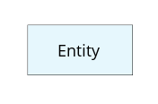
An entity may be any person, place, thing, action or concept in respect to whom, information or data is to be stored. In ER diagram, entity is being shown in the rectangular boxes.
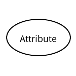
These are the properties or traits possessed by the entities, which may be define and describe. Each of the ellipse representing only one attribute is connected or linked to its respective entity. They are shown in ellipse shape.
Depending upon certain qualities & aspects, attributes may further be classified into 3 forms. These are
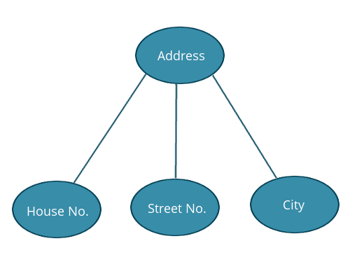
Attribute which may further be extended or branched, is known as composite attribute. For example,
Attribute which possess or store more than one value is called multi-valued attribute. These are represented by the double ellipse shape. For example,

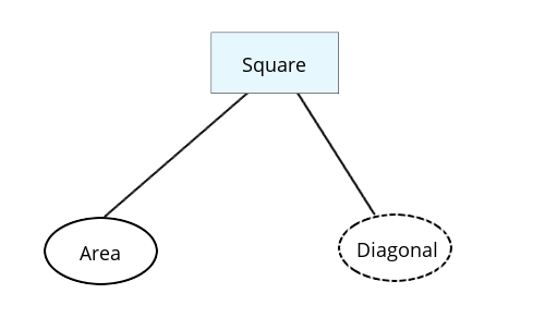
Attribute which is derived or may be inferred from the other attribute, falls under the category of derived attribute. It is shown by the dashed ellipse shape. For example
.png)
.png)
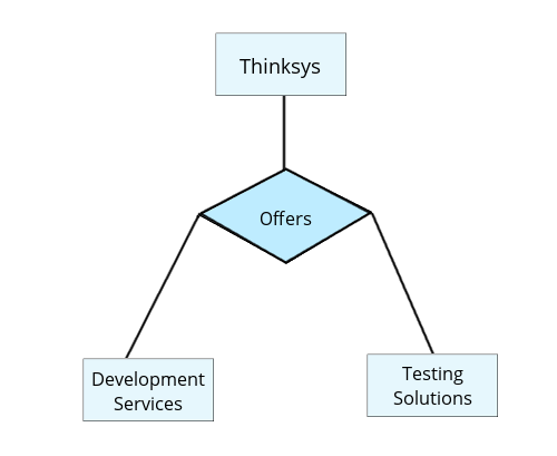
Represented by the diamond shape box, it is used to define the link or association or relationship, between different entities.
Relationships may also be classified into following forms:
It is the linking between the two entities. Based on the cardinality and ordinality, following relationship prevails in the binary relationship.
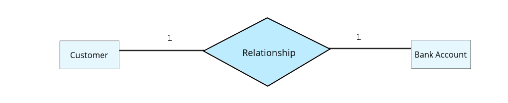
One customer may have 1 bank account only.
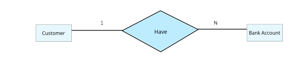
One customer may have N number of bank accounts.
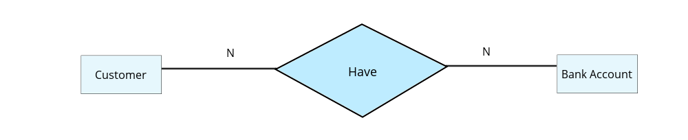
N number of customers may have N number of accounts.

N number of customers may have 1 bank account only.
It involves linking the entity to itself. For example,
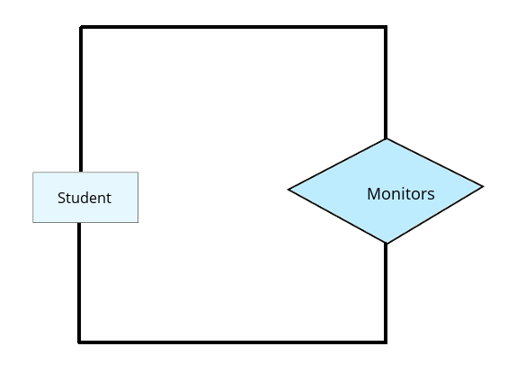
As we see, a student monitors the students.
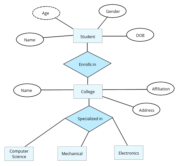
In the given E-R diagram, we have 5 entities, namely, Student, College, Computer Science, Mechanical, and Electronics.
Here, an entity, student having 4 attributes(Name, gender, Date of Birth, Age) including one derived attribute, enrolls(relationship) in a college named entity having 3 attributes namely, name, affiliation, address, which is specialized in(relationship) Computer Science, Mechanical and Electronics(3 entities).


Advertisement:


